
Devices on a network are connected physically or by wireless using radio waves, regardless of type of connection frames will have source and destination address. How can we classify networks what criteria should we use for this?
Networks can be categorized based on
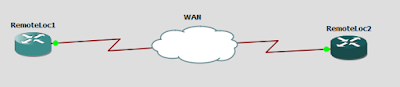
The above figure is an example of WAN, Here to geographically dispersed locations are connected this can obtained because of WAN technologies offered by SP.
In ring topology the traffic flows logically in a circular fashion. The logical token is circulated through the network only when device get token it can receive or transmit data, If a device want to transmit data it will wait for empty token, if it gets empty token it will add data and destination address and transmit the token, the receiver will collect the data and retransmit the token, below figure shows the logical connection of ring topology.

Actually devices are not connected like this, physically devices are connected as in star topology where all devices are connected to MAU (Media Access Unit) device used in token ring topology.
All the devices are connected to the MAU, internally logical token ring is circulating. This is single point of failure because if MAU goes down all networks will be down.

Even though it is easy to implement and maintain collision is the main problem of this topology. In the below figure if PC A and PC C transmit data same time assuming that channel is free for transmission, it will result in collision which will lead to data corruption. CSMA/CD (Carrier Sense Multiple Access / Collision detection) can be used to retransmit data if collision occurred. It will sense the carrier collision by this data will be transmitted only if the channel is free to transmit. These is the scenario took place in below figure both PCs assumed that channel is free and they started to transmit data and ended in collision.
If the backbone fails the entire network will be down. So how the collided frames are retransmitted to avoid the further collision? If the collision occurred it will set random back off timers for devices and only after that random timer’s devices will retransmit the frames in this way CSMA/CD works

In our example we say that random back off timers for PC A is 10 millisecond and for PC C is 20 millisecond, by this after 10ms PC A will retransmit the frame and after 20ms PC C will retransmit the frames.
We can use coax, foc to interconnection devices to network so it is scalable and flexible. Since we need a centralized device it is expensive than bus and ring topologies and it also have single point of failure that is centralized devices if it goes down all networks goes down. Lastly adding and removing devices to star topology is simple as plugging and unplugging USB devices.
 We can consider hub and spoke topology in order to reduce the WAN links between our sites, by choosing a site as hub through which traffic to other sites (spokes) flows. So don’t need direct connection between sites. Hub radiates outs to the spokes so need to have best devices at hub so that it can handle and forward traffic between the spokes. Hubs can be Head Quarters and spokes may be the branch offices, thus we can reduce number of WAN links. If we need direct connection between spokes we can add sub optimal paths.

In the above figure shows a full mesh topology used to interconnects five sites, to fully mesh five sites we need 10 links. Thus if we interconnects five sites at different locations we need 10 WAN links we though it provide optimal paths it’s very expensive to implements due to cost of WAN links. The number links needed to fully mesh any number of sites can be calculated by,
Number of linksneeded for full mesh n sites = n(n-1)÷2
If we needed to full mesh 50 remote sites we need 1225 WAN links!

In the above figure shows partial mesh topology, where sales, acct, engg are spokes to the HQ. The traffic flow between Sales and Accounting is too high so we can connect sales and accounting directly. If we full mesh this topology we need 6 wan links, by compromising network to our needs we reduced the links to 4.


Networks can be categorized based on
Categorizing Network Based on Geography
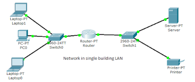
In this type we use geography as a factor to classify the networks. Based on the area a network span we can network as LAN, WAN, MAN, PAN etc.LAN (Local Area Network)
LAN is typically higher speed network than spans across single building or campus that works under single administrative control. ETHERNET is an example of LAN.
WAN (Wide Area Network)
WANs are typically slow networks compared to LANs, WANs can span across the larger geographical area, in order to maintain connections WAN technologies are used. It is used to connect LANs. WAN is under administrative control of different Service Providers (SP).
The above figure is an example of WAN, Here to geographically dispersed locations are connected this can obtained because of WAN technologies offered by SP.
MAN (Metropolitan Area Network)
MAN interconnects sites in a span of metropolitan area; this is high speed network because it used fiber optic cables (foc). MAN connection is available to users from different SP, where the SP has this foc connectivity span across the metropolitan area by underground cabling. Here SP uses DWDM (Dense Wavelength Division Multiplexing) in order separate customer’s traffic.CAN (Campus Area Network)
CAN interconnect LANs/Sites with in large geographical area (campus, industrials parks) it have higher speed because it use foc, multimode fibers are mainly used if distance is small. CAN is under administrative control of single entity.PAN (Personal Area Network)
PAN is mainly used between devices within close proximity where bandwidth is not a factor. Infrared and Bluetooth are PAN technologies. In daily life use our mobile phones, game consoles etc. come under this PANs. Bluetooth of Class 2 it can give range of 10m and 3Mbps.Categorizing Network Based on Topologies
In this type of categorizing of networks we use topology as factor. Based on this we can classify networks as ring, bus, star, and hub & spoke etc.Ring Topology
In ring topology we interconnect devices in a circular fashion, this is legacy networking scheme popular in 90’s not used in modern networks. Ring topology is mainly used in token ring and FDDI technologies. Token ring uses ring topology and supports speed up to 16Mbps whereas Fiber Distributed Data Interface (FDDI) uses fiber optic cables and hasspeed of 100Mbps.In ring topology the traffic flows logically in a circular fashion. The logical token is circulated through the network only when device get token it can receive or transmit data, If a device want to transmit data it will wait for empty token, if it gets empty token it will add data and destination address and transmit the token, the receiver will collect the data and retransmit the token, below figure shows the logical connection of ring topology.

Actually devices are not connected like this, physically devices are connected as in star topology where all devices are connected to MAU (Media Access Unit) device used in token ring topology.

All the devices are connected to the MAU, internally logical token ring is circulating. This is single point of failure because if MAU goes down all networks will be down.
Bus Topology
Bus topology is commonly used to connect Ethernet networks in mid-80’s it is inexpensive to implement, where a 50 ohm coaxial cable is used as backbone of network all devices are connected to this by T connector. Two types of cable used for this Thicknet and Thinnet. Thicknet (10BASE5) is in wider diameter with more shielding and can spread distance about 500m it is less flexible than thinnet, we use a Vampire Tap to connect devices to the backbone. Thinnet (10BASE2) is smaller and very flexible than thicknet it uses BNC connector to tap devices to backbone. Backbone should be properly terminated or degradation in data communication will occur.
Even though it is easy to implement and maintain collision is the main problem of this topology. In the below figure if PC A and PC C transmit data same time assuming that channel is free for transmission, it will result in collision which will lead to data corruption. CSMA/CD (Carrier Sense Multiple Access / Collision detection) can be used to retransmit data if collision occurred. It will sense the carrier collision by this data will be transmitted only if the channel is free to transmit. These is the scenario took place in below figure both PCs assumed that channel is free and they started to transmit data and ended in collision.

If the backbone fails the entire network will be down. So how the collided frames are retransmitted to avoid the further collision? If the collision occurred it will set random back off timers for devices and only after that random timer’s devices will retransmit the frames in this way CSMA/CD works

In our example we say that random back off timers for PC A is 10 millisecond and for PC C is 20 millisecond, by this after 10ms PC A will retransmit the frame and after 20ms PC C will retransmit the frames.
Star Topology
In this topology all devices has point-to-point connection with the centralized device. Centralized devices can be Hubs, Switches etc. Unlike hubs switches will not forward frames to all ports because it uses intelligent frame forwarding options based on the hardware address tables.
We can use coax, foc to interconnection devices to network so it is scalable and flexible. Since we need a centralized device it is expensive than bus and ring topologies and it also have single point of failure that is centralized devices if it goes down all networks goes down. Lastly adding and removing devices to star topology is simple as plugging and unplugging USB devices.
HUB and SPOKE topology
Full Mesh topology
We can consider that full mesh is just opposite to hub and spoke where more WAN links are used to provide maximum optimal paths. This is not a scalable solution and it is expensive too.
In the above figure shows a full mesh topology used to interconnects five sites, to fully mesh five sites we need 10 links. Thus if we interconnects five sites at different locations we need 10 WAN links we though it provide optimal paths it’s very expensive to implements due to cost of WAN links. The number links needed to fully mesh any number of sites can be calculated by,
Number of linksneeded for full mesh n sites = n(n-1)÷2
If we needed to full mesh 50 remote sites we need 1225 WAN links!
Partial Mesh Topology
Partial mesh can be thought of compromising between full meh and hub and spoke topologies. It is similar to hub and spoke topology where direct links between spokes are added based on traffic pattern between spokes.
In the above figure shows partial mesh topology, where sales, acct, engg are spokes to the HQ. The traffic flow between Sales and Accounting is too high so we can connect sales and accounting directly. If we full mesh this topology we need 6 wan links, by compromising network to our needs we reduced the links to 4.
Categorizing Network Based on Architecture
In this we are classifying network based on how the devices get resources from the network, it can be from server or client. So what is this server or client? We can say Client is the device that requesting for resources in the network where Server is the device that giving the resources, if it is a file server it will have all the files or databases which is shared to all users in network or it will have the user restriction based on security. Mainly we can classify this to- Client-Server Architecture
- Peer-Peer Architecture
- Mainframe-Terminal Architecture
Client-Server Architecture
In this architecture we have clients and all the resources is shared by Servers, it can be file server, databases, user accountings needed for the network. Clients can be a user device that is asking for services or resources, Server will give the resources to the clients. Servers is the specialized devices to do certain tasks which uses special Networking Operating Systems that have certain software packages for the servers to do their tasks some examples are Windows Server OS, Mac OS Server Version, Linux Server (Redhat) etc. It is single point of failure design if the server goes down client don’t get resources so we need to design redundant network.
Peer-Peer Topology
What do you mean by Peer? Peer is the devices which can act as server and client. If a PC is holding files to all other devices network and it is accessing printer connected to other Laptop in the network then both is acting as a peer. To make a peer device we don’t need Networking Operating Systems. We don’t need specialized servers for a small featured network peer-peer-architecture is good because it’s inexpensive and drawback is it doesn't provide security.
Thin-Client Architecture
It is similar to mainframe terminal architecture but thin-client is more popular nowadays in large scale networks. Terminal devices connecting to mainframe is called dumps because it has no processing power(no processor, have input/output devices). All logical processing work for dump devices is done by the mainframe devices which have large processing power .Thin-client architecture can be implemented by two ways hardware or software. Hardware Thin-Client architecture is more popular for large scale networking demands; it’s inexpensive and consume less power. RDP (Remote Desktop Protocol) developed by Microsoft, ICA (Independent Computer Architecture) developed by Citrix are two popular thin-client protocols.Jas Jashim Author and Founder of ccnaguru.com.He is electronics and communication engineer by education, working in networking field.Started this blog as an hobby to help you in ccna studies.
1 comments:
Click here for commentsHi bro, why the tree topology and hybrid topology is not listed in your topology section?
ConversionConversion EmoticonEmoticon